Manufacturers
Cut your machining and finishing costs with sintered components. Accurate, strong and economical.
You’ll find our
Sintered Components hard at work in an amazing variety of applications such as cars, door locks, appliances, farm equipment and power tools.
Using metal powders as raw materials, accurate shapes are compacted, sintered and worked in medium to high volumes at surprisingly low unit cost.
Different blends of
metal powder produce the desired qualities of strength, hardness, corrosion resistance or surface appearance. By bonding two separate shapes, parts of surprising complexity can be made, adapting the metals to the needs of the designer. A high degree of accuracy and repeatability is maintained. Strong? Even con-rods are made in
sintered metal.
You’ll find more information on
Sintered Components by clicking
here.
- Bearings
- Bolts
- Cams
- Flanges
- Gaskets
- Impellers
- Levers
- Special parts
- Sprockets
Sintered Components
Powder Metal components, hard at work in:
- Appliances
- Door locks
- Automotive
- Office machinery
- Electrical switches
- Power tools
- Sporting Goods
- Exhaust Gaskets
- Transmissions
- Farm equipment
- Garden equipment
The alloy of your choice, “moulded” to fit your design
Often, your complete parts can be made, ready to assemble, reducing your costs significantly.
Powder Metallurgy is a mass production process, so the reduction in costs can be startling –
especially compared to manual or CNC machining in-house. Even when complex parts require secondary operations
such as drilling or tapping,
Powder Metal components will give you a highly productive head start.
Indeed, many manufacturers find that
Powder Metal has the strength of wrought metal with the price
and versatility of plastics. If your processes employ cast or machined parts, consider the
Powder Metal alternative.
- Brass
- Bronze
- Carbon Steel
- Stainless Steel
- Copper Steel
- Nickel Steel
- Iron
- Iron Copper
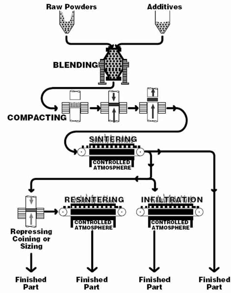
Compacting & Sintering
How powder develops the strength you need.
Metal powders are compacted in precision tooling and fed into the
sintering furnace. As the metal nears melting point, it is bonded,
resulting in ready-formed components without the expense and waste of machining or milling.
Choose your metal
Powder Metal parts can be sized, coined or repressed to exacting tolerances –
as close as 0.012 mm (0.0005”) on diameters and 0.15 mm (0.006”) on lengths.
Parts can be smaller than a shirt button, up to a component of 150 mm diameter or more.
Tensile strengths, for example, for a heat treated Nickel/Steel component may exceed
770 MPa (112,000 p.s.i.).
You may choose to specify a porosity that allows impregnation with oil or wax.
Powder Metal components can even be infiltrated with copper to aid final machining,
plating or to render them impervious for specific applications, such as in fluids.
Properties Of Sintered Bronze Bearings
Self-lubricated bronze bearings are manufactured from
bronze powder of a nominal 90/10 copper/tin composition with a small percentage of carbon. The pores are formed in the structure by the unique process of
POWDER METALLURGY (P/M) and being interconnected, serve as a reservoir for lubricant, providing a passage for flow to the bearing surface. The oil content is an average 22% by volume and is normally sufficient for the life of the bearing.
The principle of self-lubrication
The flow of oil to the bearing surface from the storage, or reservoir in the pores of the bearing, results from the slight increase in temperature, and the application of load when the shaft commences rotating. With this rise in temperature, oil is forced out of the pores, as the volumetric expansion of the oil is much greater than that of the metal. The constant flow of oil set up is maintained automatically in direct relationship to the combined effects of the temperature, load, and speed. When rotation of the shaft stops, the oil is re-absorbed in the porous reservoir.
Due to this manner of operation, the quantity of oil used is infinitesimal, and it is thus that the oil contained in Self-lubricated bearings is sufficient to give good lubrication over a period of many years.
Chemical Composition
| Copper |
87.5% minimum. |
| Tin |
9.5 – 10.5 % |
| Carbon |
0.5 – 1.5 % |
| Iron |
Balance |
| Total of other elements |
0.5% |
Physical Properties
Density varies throughout the product range.
For individual item specifications, please
contact the office.
| Density |
6.0 – 6.4 gms/cc. |
6.4 – 6.8 gms/cc. |
| Porosity |
22% by volume. |
19% by volume. |
Mechanical Properties
| U.T.S |
76 MPa (11,000 PSI.) |
| Elongation “K-Strength” |
1% |
| Constant |
117 MPa (17,000 P.S.I.) |
Comparable Specifications
Density varies throughout the product range.
For individual item specifications, please
contact the office.
| A.S.T.M |
B438 Grade 1 Type I |
B438 Grade 1 Type II |
| S.A.E. |
840 |
841 |
| M.P.I.F |
CTG – 1001 – K17 |
CT – 1000 – K26 |
Other Alloys
As noted above, the material used for our
standard range of bearings is 90/10 bronze. In instances where other materials are preferred, it may be that existing tooling will provide a bearing of the desired dimensions, Each case must be reviewed for feasibility and in all such cases volume production is a mandatory aspect.
Installation & Sizing
When calculating the
Self-lubricated bearing sizes required, the “close-in” of the
bearing during assembly must be taken into consideration. This “close-in” depends mainly on the material of the housing and also on the wall thickness of the
bearing. Soft housing materials, such as aluminium, produce less “close-in” than cast iron or steel. The “close-in” in a rigid housing that is not liable to give almost approximates the press fit.
Average Press Fit and Running Clearance are shown in Figure 1 below.
It is customary to provide a chamfer in the housing bore to serve as a lead for the
bearing. An unchamfered edge is undesirable, as it might shear metal from the bearing 0.D. thereby seriously reducing the press fit.
Self-lubricated bearings are manufactured to comply with
Australian Standards and recommended for fitting into housings made to H7 limits. Providing the housing is rigid and complies with H7 limits, and that a fitting pin to s5 similar to Fig 3 below is used, the resulting fitted
bearing bore will be F7. The
bearing dimensions ultimately selected will be influenced by the method of installation chosen, further, the bore size may be controlled by the method of installation selected.
The several methods commonly employed are:-
(i) No Tool Contacting Bore:
This method allows the Bore to close-in without restraint. The approximate amount of close-in may be determined in advance from Figure 2 below.
(ii) Combination Insertion & Sizing Plug:
The amount of close-in may be controlled by use of a combination insertion and sizing tool. The plug diameter should be approximately 0.008mm (.0003 in.) greater than the desired final bearing l.D.
Bearing must be such that the plug fits freely in the
bearing l.D. before installation. When the bearing is pressed into the housing, its l.D. will close-in on the plug.
Self-lubricated bearings generate their own oil film so there is no difficulty in extracting the plug. Upon its withdrawal, the bearing l.D. will spring back approximately 0.008mm (.0003 in.) in most cases but the exact amount must be determined by trial. See Figure 3 below.
(iii) Reaming:
Self-lubricated bearings may be reamed without destroying porosity provided a dead sharp cutting tool is used. It Is not recommended for volume production, however, since a dull tool will smear the bearing surface, closing some of the pores and reducing the self lubricating qualities of the bearing.
(iv) Burnishing:
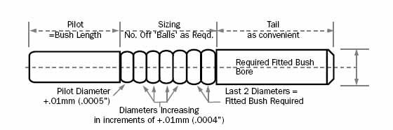
For volume production, accuracy under 0.025mm (.001 in.), a burnishing tool is recommended, like that shown below, see figure 4. Another method of accurate sizing, particularly for self aligner types of bearings, is to use a steel ball pushed through the bore; slight variation can be made to the diameters of standard steel balls by an acid etching process.
Figure 1: Shaft Diameter
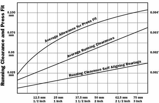
Figure 2: Bore Close-In
Bore close-in as related to wall thickness (approximate values) for simple press fit.
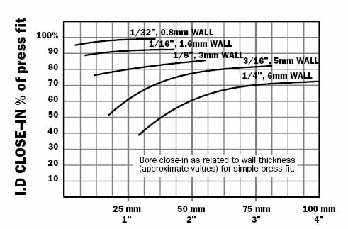
Figure 3: Combination Insertion and Sizing Plug
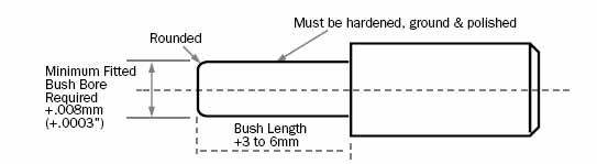
Figure 4: Burnishing Tool
Load & Application
The normal load carrying capacity of Self-lubricated bearings is expressed as PV factor (pressure x surface velocity) where-
P = the load in p.s.i. on the projected bearing area (bearing I.D. x length).
V = surface velocity of the shaft in feet per minute.
Self-lubricated bronze has a permissible PV factor of 50,000. (Imperial dimensions only)
| Shaft Velocity |
Permission Loads |
| Metres/min |
Feet/min |
Bronze |
Iron |
| MPa |
(P.S.I) |
MPs |
(P.S.I.) |
| Slow and Intermittent |
28 |
4000 |
56 |
8000 |
| >8 |
>25 |
14 |
2000 |
21 |
3000 |
| 15-30 |
50-100 |
3.5 |
500 |
5.0 |
700 |
| 30-45 |
100-150 |
2.3 |
325 |
2.8 |
400 |
| 45-60 |
150-200 |
1.8 |
250 |
2.1 |
300 |
| *60 |
*200 |
Refer to the Load/Speed chart, Fig 5 below |
| * For shaft velocities over 200 feet per minute refer to the load speed chart, Fig 5 below. |
Factor of Safety
The load speed chart is based on normal usage where lubrication is supplied by the bearing itself. The chart provides for a limited factor of safety. Where adverse operating conditions exist, however, the Safety Factor required may be as high as 4. A generous Factor of Safety should, of course, be provided where continual operation is essential.
Conditions Which Increase Permissible PV
i.e. permit a greater load or higher velocity in the order of importance, 1 to 4.
- Shaft Hardness and Finish: A hardened or chrome plated shaft ground to a finish of 0.3 micron or better, will allow much closer bearing clearances, decrease wear on both bearing and shaft, and ensure trouble free operation over long periods.
- Additional Lubrication: Pressure lubrication or extra oil supplied from a reservoir or pump will allow a much higher PV.
- Cooling: Forced air, oil circulation or other means of cooling the bearing increase the permissible PV factor.
- Instantaneous Loads: or loads of short duration (shock loads excepted) increase the permissible PV factor.
Conditions Which Reduce Permissible PV
i.e. reduce the load carrying capacity or permissible velocity.
These same conditions adversely affect all bearings, regardless of type or make, and are here enumerated as a reminder of normal bearing practice.
- General Conditions
Poor shaft finish, out of round or soft material, dust, grit, moisture and corrosive fumes adversely affect PV.
- Low speeds, continual start-stop operation, oscillatory or reciprocating motion.
While Self-lubricated Bearings are less affected than solid materials, the foregoing conditions reduce the permissible PV factor.
- High Speeds.
Continuous operation at high surface velocities reduce permissible PV. Moderately increasing bearing clearances may offset this loss in PV.
- Shock Loading.
May reduce permissible PV by as much as 50%.
- Extreme Temperature.
Abnormally high or low operating temperatures affect both the actual shaft clearance and the physical properties of the lubricant.
- Extreme Bearing Clearance.
Excessively close bearing clearances (as might occur in precision tools) or extremely loose bearing clearances (as might occur where alignment is a consideration) adversely affect permissible PV
- Shaft Runout, Deflection or Misalignment.
These conditions impose an unequal load on a bearing surface and reduce permissible PV. However, increasing the bearing clearance or using a self aligning spherical bearing will frequently eliminate excessively high localized loadings and help to maintain permissible PV at normal values.
- Revolving Bearing.
If a bearing revolves at high speed on a stationary shaft, centrifugal force will result in a loss of oil on the bearing surface and reduce permissible PV.
Thrust Bearings
The permissible PV factor for
thrust bearings is normally of the order of 10,000. Immersion in oil, intermittent loading and, especially, forced circulation of oil permit higher values.
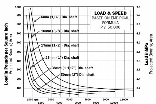
Sintered Bronze Bearings load chart (PV=5O,000)
Approximate load on projected bearing area permissible with given speed and shaft diameter.
Figure 5: Revolutions Per Minute (RPM)
Machining of Sintered Bronze
In conclusion we would stress that
Sintered Metals are not really difficult to machine if you abide by the rules particularly in regard to the sharpness of the cutting edges. A dull tool which will still do a good job on a cast or wrought metal is not necessarily sharp enough for a
sintered material.
THE AIM and objective of the
powder metallurgy industry is to eliminate machining wherever possible, and to produce the various components to the finished shapes; unfortunately occasions do arise when this is not possible, because of side holes, tapped holes, undercuts, re-entrant angles, or when quantities such as sample lots for pilot production do not warrant expensive tooling, and these parts must be produced from blanks.
Unfortunately, one of the most important features of
Sintered Metal, its inherent porosity, causes some machining difficulty by presenting a discontinuous surface to the edge of the cutting tool, thereby causing the cutting edge to be subjected to a series of impacts as it leaves a pore area and re-enters the metal. These impacts cause the tool to become dulled, resulting in poor finishes, and in the case of
oil impregnated bearings, smearing over of the interconnecting pores so preventing the flow of oil from the inner pores.
The answer to this problem is to use dead sharp cutting tools preferably of the harder grade of Tungsten Carbide, high speeds and fine feeds.
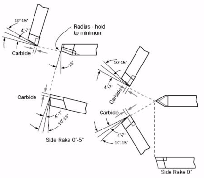
- TURNING: For turning we recommend cutting speeds of 100 metres per minute (350SFPM) and feeds of 0.025mm to 0.1 mm per revolution (0.001” – 0.005”) with tool profiles as shown in Figure 6. When rough machining is necessary and surface porosity is not a requirement, surface speeds of 150 metres per minute (500SFPM) may easily be achieved.
- DRILLING: Drilling can be carried out at speeds of 20 metres per minute (70 SFPM) and more, using HSS drills; compressed air is recommended for cooling and swarf clearance.
- TAPPING: Tapping is readily accomplished and once again compressed air is used for cooling and swarf removal. In this particular operation we would strongly recommend special tapping oils be used. Excellent results have been achieved with these commercially available products.
- COOLANTS: It will be noticed that we have not recommended any coolants other than compressed air as contamination of the impregnant oil is undesirable. In any case, re-impregnation of all components is recommended after machining operations, to overcome any possible loss of lubricant.
Tools For Machining
Moulding in Place
Sintered bearings, due to their porosity, can be readily moulded into rubber, die casting & plastics. When required for this purpose please order DRY bearings. Impregnation is obtained by submerging the entire part in oil heated to approximately 80° C for 30 minutes. The bearings being porous, readily absorb the oil.
Removing the Oil
To remove all the oil from
Oil-impregnated Bearings, simply immerse it in an active oil solvent, such as clean lead free petrol or trichlorethylene. Two or three hours should be allowed and the solvent should be changed two or three times, as needed during this period. Allow to dry by evaporation. Necessary ventilation precaution should be observed.
Storage
Oil-impregnated bearings can be stored indefinitely in suitable containers. Wood, ordinary paper and cardboard are not suitable since they absorb oil from the bearing. Properly stored in metal or plastic containers and protected against dust,
oil-impregnated units retain their oil supply indefinitely.