
Why is Vacuum Impregnation Performed on Powdered Metal Parts? – PM Distributors Pty Ltd
When a powder coated part ‘gasses out,’ its shell-like membrane is compromised. Just where is this trapped gas coming from? The component has been scrubbed clean, so there’s not a speck of dirt to worry about, nor is there a single rough edge. Maybe it’s the metal, a castings issue that’s causing surface porosity? Enter vacuum impregnation technology, a process that’s designed to seal those micro-pores.
Vacuum Impregnation Plugs Leaks
Powder coating processing has several procedural advantages on its side. Yes, this is an environmentally-friendly finishing technique, one that produces an impenetrable shell. It’s also a relatively simple coating process, at least when the equipment is installed optimally. So where does vacuum impregnation fit into the production chain? Well, this is a pre-production operation, a stage that’s implemented before the electrostatic adherence phase. Basically, this operation is intended to seal the microscopic pin holes in a metal component. It begins by inserting the workpiece into a pressure vessel. Air is drawn out of that containment unit and an anaerobic sealant is channeled into the resulting vacuum. In effect, that microscopic material ‘plugs’ the leak paths on the surface of the cast metal component so that the porosity issue is solved. Once those near invisible porous metal exterior planes are fully plugged, the finish can harden as a smooth membrane.
Why is Component Porosity an Issue?
Manufacturing technology is incredibly advanced. Unfortunately, there are still process imperfections to deal with in the metal castings industry. Most of the time, those imperfections go unnoticed. The part is machined and polished after the casting has been ejected. It fulfils its purpose in a mechanically tough application, perhaps as a crankshaft or power transmission linkage. However, surface porosity is not an option if the workpiece in question is entering a powder coating oven, a place that relies on uniform temperature distribution during the powder fluidization phase. All of a sudden, those pin holes make themselves known. The heat, a thermal load that melts the powder and sends it flowing across the metal surface, is being interrupted by the gasses escaping from those tiny pores.
Outgassing surfaces corrupt powder coated finishes. They leave small pinpricks in what should be a perfectly sealed thermoplastic skin. Water can penetrate those openings, as can other corrosive liquids. That’s why a vacuum impregnation pre-processing phase is employed. It seals the part and ‘plugs’ those holes before the powder coating is applied. Found sometimes in aluminium and zinc metal castings, and as gas cavitation defects and oxide film production errors, casting porosity is a curing oven’s enemy, but a solution exists in the form of vacuum impregnation technology.

Self-aligning bearings function as automatic imbalance compensators when ailing shafts deviate from their angular norm. Granted, the device looks much like a standard bearing. There are rings, rolling elements, and an empty middle section for a shaft. A closer look, though, reveals a curved inner surface on the outer ring, plus two sets of ball bearings. Just how does this unique device architecture correct misalignment errors?
Deflecting Angular Errors
The inner ring of a self-aligning bearing uses two grooves. Two sets of rolling elements then occupy those inner channels. Above the paired balls, a concave race surface glides along the spherical array. This is where the misalignment feature enters the mechanics of the design. Simply put, that outer ring, its curved inner surface, deflects ever so slightly when a shaft moves out of alignment. The inner ring accommodates the error, which is unavoidable since it’s coupled to the shaft, but the outer ring corrects that angular deviation by acting as a compensation ring, a component that deflects around the bearing axis. When this compensation action takes place, the radial imbalance is offset and the equipment housing avoids shaft movement stress.
Self-Aligning Bearing Benefits
Imagine the device operating when severe shaft imbalance is threatening a motor or power transmission train. The mounted rod is moving eccentrically, yet no damage occurs to the outer machine components. That inner ring and its twin set of ball bearings are paralleling the misalignment error, but the curved surface inside the outer ring is compensating for the jagged movement. Thanks to this design, continuous static misalignment problems are offset. Likewise, dynamic radial errors are counteracted, with the concave race skating axially up and down the spherical rollers in a sinusoidal manner so that the external parts remain unstressed and wear free. Frankly, that kind of wear is hard to avoid. The spinning parts cause wear, then vibrations aggravate the ageing effect until the coupling device connecting the power transmission train is pushed off centre. Fortunately, self-aligning bearings still operate properly when these mechanical forces have their way.
Self-aligning bearings leverage a property that lives inside every ball bearing. Built to race down the twin rings in a single direction, at right-angles to the shaft, the spheroid profile gains access to a second dimension when a concave surface is present on the outer ring. Aided by an extra set of balls, the outer ring imbues the device with the ability to move along a second axis. Of course, that deflection angle is small, but it’s more than enough to correct a shaft’s misalignment problems while quietly delivering thrust-free performance.
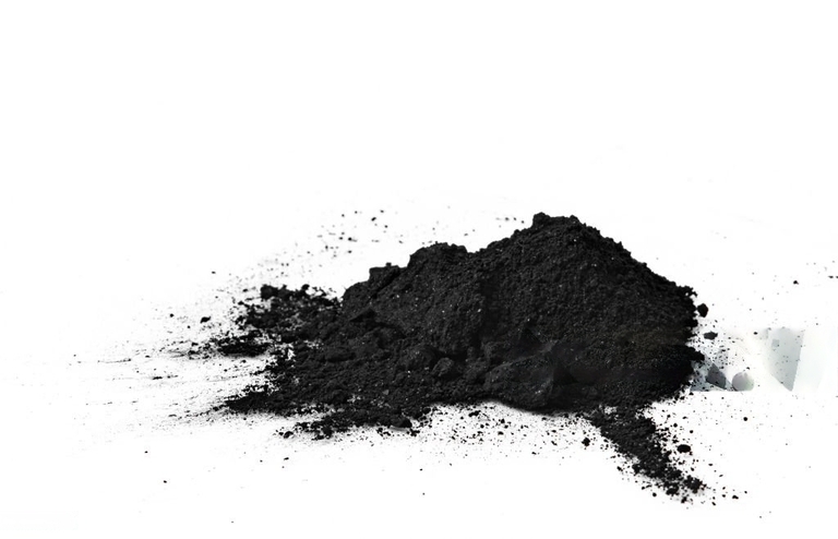
Metal powder is created by the act of powder metallurgy. This means that any variety of metal, such as steel or iron, is compressed before being sintered to form a metallurgical bond. From there, the metal powder is used in a variety of different applications around the commercial world. We’re pretty sure you never knew just how much this process is used on objects you interact with in your everyday life. Let’s take a closer look at metal powder and see the benefits as well as different kinds that are available on the market.
All about Metal Powder
Metal powder is actually utilised in a variety of different ways. The primary way that metal powder is used is for the commercial coating of various products. Metal powder is also used in two other industries: additive fabrication and soldering. Let’s take a mini-detour to find out what metal powder does for each industry.
Powder Coating – Metal powder can be added to paint in order to give the end result a more metallic finish. Metal powder in paint will make a product look reflective, decorative, and a little more durable.
Additive Fabrication – This style of metal powder usage is largely consigned to the 3D printing industry. This exhaustive process includes heating up the metal powder into a liquid stream, thus atomised by gas. The heated metal powder will then be converted into microscopic spheres which help to create the 3D objects printed by 3D printers.
Soldering – Close to sintering, soldering involves heating up metal powder so that it turns to liquid in order to fill out any pits or irregularities in the primary object.
Different Kinds of Metal Powder
There are different varieties of metal powder and each has its own distinct performance and functions. With its wide range of uses, companies need to have several options. Listed below are some of the most common metals used in metal powders.
- Aluminium
- Brass
- Bronze
- Copper
- Graphite
- Iron
- Stainless Steel
- Zinc
As you can see, there are a wide range of options here that each can fulfil a different need. Whether used for a 3D printing company or on the production line of a manufacturer and distributor, metal powder can make a difference.

When a shrewd bearing manufacturer takes advantage of sintered components, new product lines gain tailor-designed features and functions. To put it another way, customised bearing requirements are readily expedited when that manufacturer embraces sintering technology. First of all, even the most professionally equipped machine shop uses a subtractive process to fabricate its mechanical bearings. Sintered bearings are made from a powder compaction and heating technique, so there’s no waste.
Material Waste Reduction
While this custom-built feature may not seem like a benefit, one that’s felt by the customer, there are advantages to this naturally eco-friendly process. Costs are driven down because there’s no subtractive waste left over. If there are any particulate detritus or bearing lubricant traces left behind, the materials are recycled.
Satisfying Customised Bearing Requirements
Next on the agenda, a prized customer is seeking a specially configured bearing. Sintered components are imbued with a material-trapped lubricant. If the loading profile of that customer’s equipment is in flux, the manufacturing line can alter the lubricant ratio with a few adjustments to a control station. The heat, pressure, even the lubricant quantity and type, are all governable at the fabrication stage. Better yet, the newly tailored parts will all leave the production line with those altered performance characteristics fully intact, for the sintering process is designed to repeatably imbue every batch-fed bush and bearing with absolutely identical load handling specs.
Assorted Musings on Sintered Components
The addition of a flange or a collar, the widening of the diameter of the bearing or the addition of a special keying mechanism, sintered components reliably adapt during the fabrication stage so that they immediately satisfy those needs. Traditional bearings, assembled from many components and exposed to exotic heat treatment stages, don’t necessarily emulate that repeatability factor, not when the heat or machining adds cold work stress and surface hardened variability to the mix. Built to bend to the will of pressure-based machinery and a tight-tolerance heat cycle, the high-strength, high-precision sintered parts obey those direct application mechanism without incurring work stress. Likewise, a customised bearing won’t lose its key friction-handling parameters when the compacted metal particles assume more volume or a different operational profile.
Based on particle compaction technology and heat-locked manufacturing science, sintered components don’t suffer from the same issues that trouble subtraction fabrication processes. Indeed, customised bearings adapt to this production equipment with ease, without the need for heat treatment alterations or a subsequent change in an in-situ lubricating agent. Essentially, then, these tailored alterations take place at the factory, at a site where the custom-designed alterations can proliferate in batches so that the changes to the bearing are repeatedly and reliably incorporated.
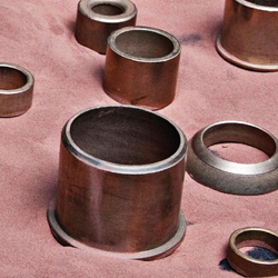
Compacted powder metal filters and silencers are manufactured as all metal products. There are no fallible moving parts or different materials to fabricate, no peculiar flow models to predict. In lieu of a multi-component architecture, a single porous metal part filters numerous fluids mediums. Made from bronze, from copper-nickel and stainless steel, poriferous sintered strainers are endowed with unique fluid-processing properties, including an innate durability feature.
Durable All-Metal Filters
When torturous conditions propel high-temperature gases down a sealed channel, a standard screening solution feels the strain. All-metal sintered filters and silencers endure under these parts-corrosive conditions. The disc or cone-shaped powder metal product allows a selected fluid to travel through the sintered mass, but suspended particulates are removed from the stream. Furthermore, the powder compaction process is finitely variable, which means filter permeability can be adjusted. When the metal sintering process addresses filtering needs, a typical bore pitch of 10 to 50 microns is easily achieved.
Handling Pressure Differential Extremes
Metallurgical technology governs pitch bore diameter, durable alloys manage corrosive chemicals and soaring temperatures, and mechanical strength counterbalances tough pressure differentials. The sourced material is typically a member of an industrially toughened bronze alloy or stainless steel composite. A similarly hardy copper-nickel blend can also offset the mechanical stresses created by the tremendous pressures that exist in many of today’s processing environments. While other manufactured products would wilt under the pressure, single-piece sintered filters retain their intended functions. Better yet, a unibody sintered filter naturally maximises fluidic diffusion while containing that pressure differential behind its porous but rigid mass.
Charged with Fluid Silencing Characteristics
Sintered metal filters are built to strip away dynamic stresses as effectively as they deal with liquid-suspended particulates. As that force-cancelling function commences, gaseous loads are nullified, air exhausts are silenced, and dynamically funnelled noise is muted. In essence, these products are built for pneumatic, chemical, and hydraulic systems, places where propagating vibrations must be effectively reduced until they comply with industry-accepted noise regulations.
In oil-filled hydraulics and pneumatic equipment, sintered metal filters handle large pressure differentials while removing the piped contaminants that are flowing in that system. The powder metal compacting process produces screen bore diameters that vary within a few microns, so chemical treatment plants also employ these corrosion-resistant filtering solutions. Finally, noise emission control falls under the jurisdiction of this metal-only filter type, with the porous alloy sieves dismissing the pressurised air and other gases so that the exhaust from the filter is properly silenced. That last feature targets air compressors and other air-powered equipment.
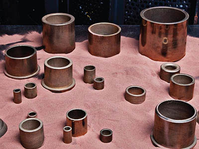
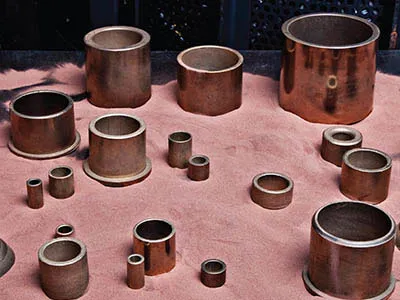
Self-lubricated bearings ceaselessly counteract sliding element friction. That’s because, unlike their high-maintenance counterparts, this self-sufficient bearing type doesn’t require a supplementary oil feed system. Instead, the all-important lubricant, the oily stuff that produces a thin film around the bearing parts, is part of the machine component. Granted, the advantages of this friction-diminishing arrangement are many. They include that just mentioned low maintenance benefit, but just how do self-lubricating bearings work?
Alternative Mechanical Solutions
Some perspective is needed before we can go further. A mechanical bearing is a stressed device, and it’s the job of the lubricating agent to manage that stress. Imperceptible flaws on the sliding elements, high rotational loads, and several other contributing factors are pushing the rings and moving parts hard. The solution to this frictionally oppressive setting is to introduce a lubricant, a slippery film whose sole purpose is to “grease the wheels,” as it were. Submerged in an oil bath or connected to an oil-feed line, engineering methods ensure the lubricant is at hand, but they can and do fail. What if there was a bearing type that possessed a self-lubricating capability, though?
Self-Lubricating Bearings: The Operational Basics
The concepts proposed here are fascinating. For instead of employing a dense and impenetrable base material, we’re looking at metals and polymers that are endowed with a porous structure. There are the sintered bronze alloys we’ve already covered. Basically, the powdery metal is compacted into its product shape while it’s simultaneously impregnated with a lubricant. As the bearing enters its operational life, microscopic quantities of the slippery liquid are dynamically transferred to the moving parts until that uniform oil membrane covers every moving surface. How, then, does this process take place when the sintered bearing first enters service? A break-in period is mandated. That “priming” stage recommends a low-speed operational run so that the oily film is properly distributed.
Porous sintered materials and bronze-based capillary action lead the way when we’re referencing metal products. There are, of course, other self-lubricating bearings on the market. PTFE, a multisyllabic polymer that’s branded under the Teflon label, imbues thermoplastic components with a certain degree of lubricity. Then there are the oil-impregnated plastic bushings that benefit thermoplastic components. These parts use reinforced plastic fibres and a solid lubricant, as trapped inside the closed cells of the polymer material, to attenuate friction. Finally, there are graphite plugged bronze variants, bearings that rely on the flat micro structure of this commonly used form of carbon. Plastic or graphite, though, these alternatives don’t pack the lubricating power of a toughened, sintered bronze bearing.
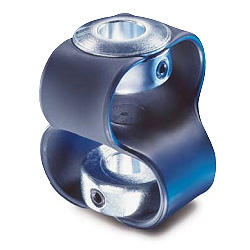
Technical terms always cause a raised eyebrow while you try to decipher the term. K-Couplings are no exception, so let’s lay down a definition that explains this engineering term. Essentially, this shaft coupling is designed as a drive chain compensation mechanism. In other words, if there’s a misalignment error between two powered shafts, a flexible K-coupling correct will correct the problem. With that said, what does one of these devices look like?
Designing K-Coupling Profiles
Two thick loops of polyurethane form the unibody product so that it absorbs shock radial forces. The elastomeric material is also fitted with a bookending pair of zinc-plated hubs, which function as shaft anchoring assemblies. In the looks department, the shaft coupler resembles a figure-of-eight rubberized device, with the two loops offset from each other by ninety degrees. Finally, on the end mount components, the hubs, there’s an inbuilt keying arrangement, a feature that adds either Allan screws or flattened shaft keyways to the mechanism’s build.
Their Alignment Correcting Role
In engineering terms, two gear or motor drive axles must be correctly aligned. If mechanical alignment is maintained, radial momentum is transmitted efficiently. Unfortunately, this theoretical ideal can’t always be achieved, not without an expensive overhaul, at any rate. This is a scenario where elastomeric couplers excel. Lateral alignment problems are solved by adhering to this flexible corrective solution, as are any angular deviation glitches. In other words, this shaft connecting device utilises its flexible urethane loops as a shaft offset correction mechanism.
Other K-Couplers Advantages
The base of one motor is fractionally higher than its companion pump shaft. Over in the corner of the plant room, another shaft is mounted on an imperceptibly canted pedestal. Although the two device assemblies are transmitting power, an invisible offset is placing a strain on the bearings and mount. Fortunately, the K-Coupling is compensating for any off-balance loading. That same arrangement is also acting as a vibration dampening or isolating service, which is a critically important feature when one section of the power train is discharging lots of mechanical noise. The polyurethane loops stop the vibrations, isolate the noise, and quiet the system.
Ultimately, K-Couplings are employed as vibration and positional compensators in a drive chain. They continually adjust, even when an angular misalignment issue is severe. Thrust loads or angular errors, lateral alignment problems or vibration-prone drive trains, all of these problems are correctable when a twin-looped elastomeric K-Coupling is installed between two shafts.

Distinguished by numerous metallurgically superior features, Super Oilite is a premium bearing type. The material again employs powder metallurgy science, but this time it’s an array of proprietary manufacturing methods that earn this self-lubricating material a place of prominence inside the toughest industrial drive systems. We start with the strong ferrous backbone.
Iron-Framed Super Oilite Bearings
The emphasis is necessarily on quality when bearing materials are being developed, which is a problem with some sintered materials. Frankly, a lesser sintered product can break down quickly if it’s not designed with a toughened metal base. Super Oilite bearing materials solve this issue by reinforcing the metallurgical element. In this case, the sintered bronze is replaced by a stronger iron substructure. Granted, the powder metallurgical process produces highly wear resistant bronze sintered materials, but the substituted iron adds strength and hardness to an already sturdy bearing metal.
Recognising a Self-Lubricating Standard
If Oilite is a robust self-lubricating bearing family, a bronze part that uses sintering technology to greatly reduce driveshaft stress, then that line of reasoning implies the ‘Super’ descriptor is merited by intelligently swapping out the bronze base metal for iron. True, the more robust metallurgical element plays a significant role here, but there’s more to consider. First of all, all Oilite products, branded as they are, must be manufactured according to the highest possible production standards. To put that statement in perspective, these are sintered material, just like any other, but they’re exposed to greater die compaction pressures than other self-lubricating bearings.
Better Than Their Generic Counterparts
Essentially, there’s a thematic thread running through Super Oilite bearing materials. There’s that already mentioned enhanced compression equipment configuration. That same premium build factor touches every other process phase, so expect a superior lubricating agent, one that mirrors the exceptional sintering procedure. Thanks to these intelligently implemented manufacturing techniques, plus the equally capable production equipment, close dimensional tolerances are achieved, as is a metallic substructure that assures proper bearing lubricity. It’s the vacuum impregnation process and an equally capable belt furnace station that makes the difference.
Made possible by a production setup that pushes sintered engineering science to the limit, Super Oilite bearing material does leave the equipment line as a self-lubricated drive bearing, but it’s a bearing material that has little in common with any generic bearing alloy. In place of a mediocre product, these branded bearings use iron in the powder metallurgical process, plus all of the necessary engineering methods that guarantee a premium grade self-lubricating bearing product line.
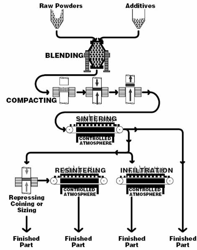
A map of sorts determines just how sintered components are manufactured. It describes an engineering process, though, not some diagrammatic portrayal of a geographical area. On that diagram, the powder metallurgy process illustrates, in steps, the procedures used to transform powdery metal feedstock into refined final products, say a sintered bearing or a brake pad for an automobile. Let’s navigate this processing map.
Following the Powder Metallurgy Process
In engineering parlance, a block diagram greatly simplifies an overwhelmingly complex series of manufacturing steps. That’s what this “map” is designed for, to clearly illustrate the powder sintering production line. And, when we say “line,” that’s likely misrepresenting the nature of this diagrammatically represented blueprint, for there are branches and convergences taking place on this processing chart, not just a linear manufacturing procedure. It all begins with the raw materials, with the metal powder and additives.
Powder Sintered Procedurals
To use a quick metaphor, if the powder metallurgy process is a tree, then the raw materials are the roots of that tree. This is the powdered bronze, a popular bearing material that’s chemically deposited or shredded through a special grinding machine. In our first branch on that tree, the powder metal mixes with additives. What are those additives? In the example we’re charting, the mix adds a waxy lubricant. From here, the blend enters a large mechanical compaction stage. Die presses, core rods, and mandrels transform the blended mix into a near solid material. Finally, as the material leaves the compaction block of the diagram we’re describing, it travels into the sintering area, a stage that heats the bronze/lubricant amalgamate until it becomes a solid metal, one that still exhibits a semi-porous microstructure.
An Indispensable Bearing Manufacturing Process
Ideally, a friction-mitigating bearing would have no moving parts, just a plain surface that magically supports a loaded shaft. The powder metallurgy process isn’t powered by magic, but it does use the material characteristics of a known metal to turn powdery piles into lubricant-infused bearings, which is a kind of magic in and of itself. Essentially, that solid alloy is ground down, then the powder metallurgy process reassembles the metal, this time with a porous structure, one that provides that essential self-lubricating feature we’ve mentioned so often in the past.
Think of the powder metallurgy process as a non-ferrous solids conversion technique. Exposed to grinding machinery, the solid bronze becomes a light powder. The procedures covered above then change the bronze particulates back into a solid bearing, except the material is now loaded with tiny pockets of slippery oil, a product profile that excels as a self-lubricating shaft mount.
Take a walk through any functional factory or warehouse and look around at the machinery that you see. Every machine in the building, comprised of any level of moving parts, will likely need to utilise bearings of some kind. Bearings allow for rotation or movement while eliminating as much stress and friction as possible. There are countless different bearings in terms of style and what they do. Today we are going to be introducing you to the self-lubricating bronze bearing. Let’s learn what these bearings are, how they work, and why you should use them.
What is a self-lubricated bronze bearing?
Alright, so this is the question that brought you here. Fortunately and unfortunately this question has a simple answer and a more elongated one. Let us start by knocking out the simple aspect of the question. A self-lubricated bronze bearing is basically a bronze bearing that has been imbued with lubrication that will be wrought out from the material when it needs to be utilised. This means that workers don’t need to spend excess time lubricating the actual bearings themselves. Now, let’s dig into the deeper answer.
How do self-lubricated bronze bearings work?
One of the most consistent sources of bearing failure in industrial applications is improper lubrication. What this means is that bearings aren’t properly being lubricated which is causing stress to build up from constant force and friction. This force and friction leads to a bearing failure that can be, at minimum, a pain the neck and at maximum a productivity killer for your business. This has led to an industry wide panic which means that workers are now frantically lubing up every bearing, whether they need to or no. This naturally brought us to an innovative piece of technology and a problem solver: the self-lubricating bronze bearing.
Now, self-lubricated bronze bearings don’t look any different than regular, non-self-lubricated bronze bearings. The difference comes at a more technical level when comparing the two. The self-lubricating bronze bearing is made up of metallic components that have a porosity rate of nearly 25%. A high porosity rate means that liquid can be transferred easier. This is where the self-lubrication comes into play. These bearings are imbued with a special kind of oil upon being manufactured. This lubing is naturally secreted from the bearing while it is in usage. Manual lubing is not necessary for these types of bearings and, in fact, could end up deteriorating the quality of the metal.